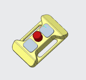
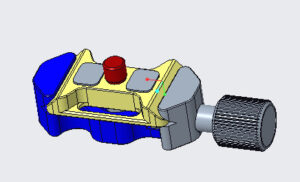
I have no idea what I am doing. But I learned that all you need is to set a clearly defined goal and work towards it. We set some goals in the previous post and here’s what I did. I took the 3D model (.stl file) I found online and went to tinkercad.com and imported it as a new project.
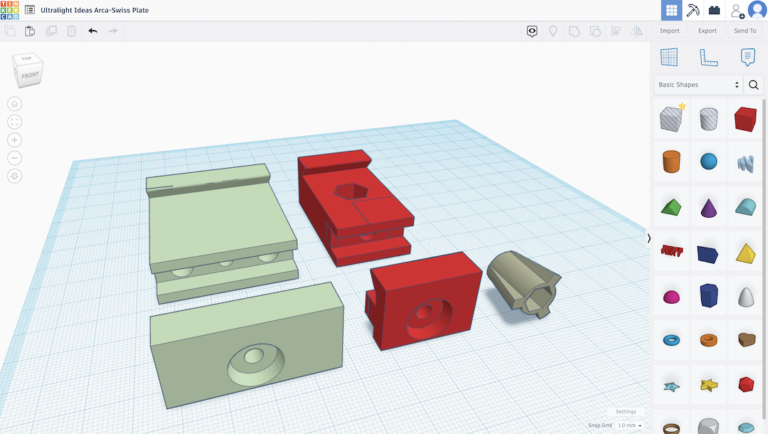
Tinkercad is a kid-friendly, free online application that lets you create or modify 3D models. You can see in the screenshot above, our reference model is in light green. From there, I created a copy of the model and started working with it using the tools on the right-hand side. This was my first-time using this application and it was remarkably intuitive. There are some great YouTube videos that explain the basic functions in under 10 minutes and I started playing with it. I felt completely safe making mistakes because of the “undo” button. I soon figured out the basics of how to cut and merge pieces together which is all I needed to know for this project. I made the changes I wanted pictured in the red model above. I saved my modified 3D model onto an SD card, popped it into my 3D printer, and waited for it to be done.
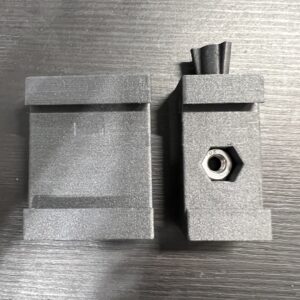
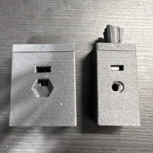
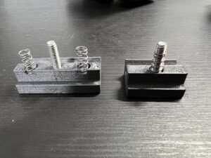
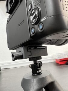
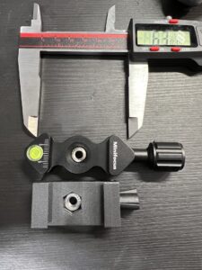
The truth is that 3D printing and tinkering isn’t a perfect science. The photos above are actually showing the seventh version of the modifications I was trying to make. Sometimes it takes small, boring adjustments to make sure everything is perfect. So let’s talk about the changes I made.
- You can see I cut the width of the original by almost half. This decreases the footprint and weight.
- I changed the securing method from bottom-up to top-down. This feels 100% more secure and truly secures the device to the ball head.
- I decreased the space for the M4 nut to fit the 7x7x3mm footprint almost perfectly. This way it doesn’t fall out and creates less play when tightening.
- I got rid of the double-spring design and used a single spring sleeved over the M4 screw. This makes it look cleaner, reduces the number of parts, and lightens the weight.
- Some smaller changes you may not see in the photos is that I changed the bore-size of the holes to have the spring flush with the M4 square nut and recess into the clamp section so it’s not moving around.
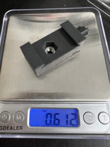
The results were better than I imagined. The total weight was 0.61 ounces (17g)! That’s a about one-third of the reference minifocus aluminum clamp’s weight. It securely clamped my DSLR camera with no issues. You can kind of see there was a slight offset when fully clamped against the aluminum plate. I saw it was due to two reasons: (1) Peak Design plates have 2mm “feet” that raises the height of where it meets the clamps. (2) The 3-D printed parts don’t fit perfectly together. This is intentional because if you tried to print a perfectly fitted piece, they wouldn’t be able to slide in together. So it’s a design feature that can’t be avoided. Finally, we reduced that crazy long 98mm down to 63mm! This fits the footprint of our product perfectly making it easier to place on or in a backpack. So now that we have a functioning prototype, what’s next?
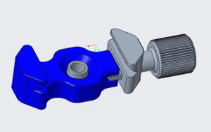
We reached out to a manufacturer on Alibaba and I had the great fortune of coming across the engineer of the company. I sent him a photo of the minifocus aluminum clamp and it turns out they actually manufactured the product (score!). We started chatting and he sent me these engineering drawings above of the current design. I shared with him photos of this project and we decided to order a custom sample. We’re really excited about how it turns out and we’ll be sure to share it with you guys in the next post and video. Feel free to drop any comments for any ideas or suggestions you want in the final design. Stay tuned for final piece in this series.

